CAD模型简化及优化工具_CRTech SpaceClaim for
Thermal Desktop®
CRTech SpaceClaim®
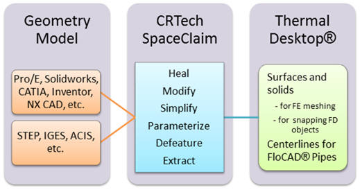
可以导入所有主流CAD软件(包括Proe、UG、Solidworks、Inventor、Catia等)的零件和装配体;并能以简单操作完成螺纹、螺孔、倒角等CAD细节的批量快速移除工作;完成复杂几何体的简化与修补工作;并可以用其它CAD软件没有的“直接建模技术”快速添加、调整、修改CAD模型。经调整后的CAD模型可以被Thermal
Desktop使用以快速生成热模型。
此外,新增模块
Mesh Generation for SpaceClaim
为用户提供了更强大的热模型生成能力,包括高级网格生成(例如,使用矩形单元生成模型、对局部网格密度进行控制、划分非常规几何体、多体之间的合并与匹配等),包括在几何环境中定义热分析参数(如属性、辐射分析组、接触区与加热区)和网格生成后的Thermal
Desktop模式的再编辑等。这些设置能自动保存并在几何设计发生变化后自动更新。
CRTech SpaceClaim是SpaceClaim
Corporation’s SpaceClaim Engineer®的扩展。想获取CRTech
SpaceClaim模块的更多信息或想获得试用软件,请与北京红缨联合科技有限公司联系。